
Cisco ASA Active/Standby Failover Configuration
The security appliance supports two failover configurations: Active/Active Failover and Active/Standby Failover. Each failover configuration has its own method to determine and perform failover. With Active/Active Failover, both units can pass network traffic. This lets you configure load balancing on your network. Active/Active Failover is only available on units that run in multiple context mode. With Active/Standby Failover, only one unit passes traffic while the other unit waits in a standby state. If Active unit fails, secondary will take over and starts forwarding the traffic. When Secondary becomes active, it will also change it's interface IP address and mac address as well. In Active/Standby configuration, virtually all of the configuration from the active unit is replicated to the secondary unit through a failover cable.
This article focuses on how to configure an Active/Standby Failover in ASA Security Appliance.
License Requirements
Failover units do not require the same license on each unit.
Older versions of adaptive security appliance software required that the licenses match on each unit. Starting with Version 8.3(1), you no longer need to install identical licenses. Typically, you buy a license only for the primary unit; for Active/Standby failover, the secondary unit inherits the primary license when it becomes active. If you have licenses on both units, they combine into a single running failover cluster license.
How Failover Licenses Combine (examples)
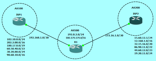
Now let's dive in to the configuration of Active-Standby Failover. In this document we will be using the Cisco ASA with image of version 8.4(x) and topology as described in the below image.
 ASA1
ASA1
On the standby unit, we just need to do the following configuration, and the rest will be automatically replicated from the Active device.
ASA2
• Optionally, also replicate the HTTP sessions
• Change the prompt to show Primary or Secondary and Active or Standby.
• Enable failover shared secret
A few differences exist between the units based on which unit is primary (as specified in the configuration) and which unit is secondary:
In the show ip address command, we can see that the IP address are showing twice. now you may wonder, why it is showing twice?
First section is "System IP Addresses" and the Second section is "Current IP Addresses".
In the above scenario, in case the Primary ASA fails, we can observe that ASA2 which is now Active ASA, will show the System IP addresses as the IPs configured manually on it's physical interfaces, and the Current IP addresses will be of the ASA1 interface IP addresses, which the firewall is using currently.
The "active" unit uses the "system" IP addresses and the "standby" unit uses the "standby" addresses. If failover happens, the normal routed interfaces on the new active unit will use the system IP address.
The addresses configured on the lan and stateful failover links do not change or swap
This article focuses on how to configure an Active/Standby Failover in ASA Security Appliance.
Prerequisites
Hardware Requirements
The two units in a failover configuration must have the same hardware configuration. They must be the same model, have the same number and types of interfaces, and the same amount of RAM.
Failover units do not require the same license on each unit.
Older versions of adaptive security appliance software required that the licenses match on each unit. Starting with Version 8.3(1), you no longer need to install identical licenses. Typically, you buy a license only for the primary unit; for Active/Standby failover, the secondary unit inherits the primary license when it becomes active. If you have licenses on both units, they combine into a single running failover cluster license.
How Failover Licenses Combine (examples)
- If you have two ASA 5540 adaptive security appliances, one with 20 contexts and the other with 10 contexts; the combined license allows 30 contexts. For Active/Active failover, for example, one unit can use 18 contexts and the other unit can use 12 contexts, for a total of 30; the combined usage cannot exceed the failover cluster license.
- If you have 48 weeks left on the Botnet Traffic Filter license on both units, then the combined duration is 96 weeks.
- If you have two ASA 5520 adaptive security appliances with 500 SSL VPN sessions each; because the platform limit is 750, the combined license allows 750 SSL VPN sessions.
Now let's dive in to the configuration of Active-Standby Failover. In this document we will be using the Cisco ASA with image of version 8.4(x) and topology as described in the below image.

! Bring up the interfaces that will be used for lan failover (G3) and state failover (G4)
interface GigabitEthernet3
no shutdown
!
interface GigabitEthernet4
no shutdown
! Apply the IP address along with the keword "standby" and
! the standby address that will be used by the unit in standby mode
interface GigabitEthernet0
nameif OUTSIDE
security-level 0
ip address 192.168.1.1 255.255.255.0 standby 192.168.1.2
!
interface GigabitEthernet1
nameif INSIDE
security-level 100
ip address 172.16.0.1 255.255.255.0 standby 172.16.0.2
!
interface GigabitEthernet2
nameif DMZ
security-level 50
ip address 10.0.0.1 255.255.255.0 standby 10.0.0.2
! Tell the ASA that G3 will be named "LAN_FAIL" and that it will be used
! to replicate the configuration between ASA1 and ASA2
failover lan interface LAN_FAIL GigabitEthernet3
! Use the failover command to assign "LAN_FAIL" the active
! and standby IP addresses
failover interface ip LAN_FAIL 10.1.1.1 255.255.255.252 standby 10.1.1.2
! Tell the ASA that G4 will be named "LINK_FAIL" and assign the IP address for active
! and standby. Note that the word 'link' is the clue to identify this as the stateful connection
failover link LINK_FAIL GigabitEthernet4
failover interface ip LINK_FAIL 10.2.2.1 255.255.255.252 standby 10.2.2.2
! Tell this ASA that it's title will be "PRIMARY"
failover lan unit primary
! Enable failover
failover
On the standby unit, we just need to do the following configuration, and the rest will be automatically replicated from the Active device.
ASA2
interface GigabitEthernet3
no shutdown
!
failover lan interface LAN_FAIL GigabitEthernet3
failover interface ip LAN_FAIL 10.1.1.1 255.255.255.252 standby 10.1.1.2
!
failover
Optional Configuration
The above configuration is enough to run failover on ASA devices, but you could additionally configure some optional parameters for extra features.• Optionally, also replicate the HTTP sessions
failover replication http
• Change the prompt to show Primary or Secondary and Active or Standby.
prompt hostname priority stateAfter configuring the prompt, the prompt on ASA devices will look like this:ASA1/pri/act#ASA1/sec/stby#Note that the default hostname will be the same for both active and standby units, due to the configuration being replicated.
• Enable failover shared secret
failover key *****
Failover Triggers
The unit can fail if one of these events occurs:
- The unit has a hardware failure or a power failure.
- The unit has a software failure.
- Too many monitored interfaces fail.
- The no failover active command is entered on the active unit, or the failover active command is entered on the standby unit.
Primary/Secondary Status and Active/Standby Status
The main differences between the two units in a failover pair are related to which unit is active and which unit is standby, namely which IP addresses to use and which unit is primary and actively passes traffic.A few differences exist between the units based on which unit is primary (as specified in the configuration) and which unit is secondary:
- The primary unit always becomes the active unit if both units start up at the same time (and are of equal operational health).
- The primary unit MAC address is always coupled with the active IP addresses. The exception to this rule occurs when the secondary unit is active and cannot obtain the primary MAC address over the failover link. In this case, the secondary MAC address is used.
Regular and Stateful Failover
The security appliance supports two types of failover, regular and stateful. This section includes these topics:
- Regular Failover
- Stateful Failover
Regular Failover
When a failover occurs, all active connections are dropped. Clients need to reestablish connections when the new active unit takes over.
Stateful Failover
When stateful failover is enabled, the active unit continually passes per-connection state information to the standby unit. After a failover occurs, the same connection information is available at the new active unit. Supported end-user applications are not required to reconnect to keep the same communication session.
The state information passed to the standby unit includes these:
- The NAT translation table
- The TCP connection states
- The UDP connection states
- The ARP table
- The Layer 2 bridge table (when it runs in the transparent firewall mode)
- The HTTP connection states (if HTTP replication is enabled)
- The ISAKMP and IPSec SA table
- The GTP PDP connection database
The information that is not passed to the standby unit when stateful failover is enabled includes these:
- The HTTP connection table (unless HTTP replication is enabled)
- The user authentication (uauth) table
- The routing tables
- State information for security service modules
'show ip address' command on Cisco ASA
First section is "System IP Addresses" and the Second section is "Current IP Addresses".
In the above scenario, in case the Primary ASA fails, we can observe that ASA2 which is now Active ASA, will show the System IP addresses as the IPs configured manually on it's physical interfaces, and the Current IP addresses will be of the ASA1 interface IP addresses, which the firewall is using currently.
The "active" unit uses the "system" IP addresses and the "standby" unit uses the "standby" addresses. If failover happens, the normal routed interfaces on the new active unit will use the system IP address.
The addresses configured on the lan and stateful failover links do not change or swap


Comments
Post a Comment