
NSX-T Configuration from Scratch
In this blog post we'll see step by step configuration of NSX-T
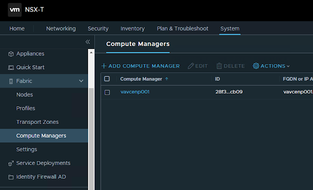
1. Add Compute Manager
a. One Overlay Transport Zone for Host and Edge Transport Nodes
b. Two VLAN Transport Zones. One for Host Transport Nodes and another for Edge Transport Node. (having two separate VLAN transport zones is not necessary, a single VLAN Transport Zone can be used Host and Edge Transport zones)

3. Create Uplink profile for Host Transport Node
In our design, we are using LAG consisting of two uplink on Host Transport Nodes. LAG is already created on vCenter ESXi hosts. Transport VLAN is the VLAN used for Host TEP IP address pool. There is no need to specify the MTU size in Host Uplink Profile, as we are using converged VDS in our design and MTU settings need to configured in VDS (on vCenter).


5. Create Host Transport Node Profile
Type: VDS (since we decided to use VDS with NSX)
Name: Select the Compute Manager from the first dropdown, and in the second dropdown, select the VDS that would be hosting NSX segments.
Uplink Profile: Select the uplink profile that we created for Host Transport Node in above steps.
IP Assignment: We can chose either static, IP Pool, or DHCP. We are using DHCP here.
Teaming Policy Uplink Mapping: In the first column, LAG1 is the Object that we created in uplink profile we created in above steps for Host Transport Nodes. In the second column, the LAG1 is the actual LAG crated on VDS (on vCenter), which is selected from the dropdown-select option.


6. Configure the Compute Cluster of vCenter for NSX.
Select the Host Transport Node profile created in steps above to configure NSX on the cluster.

7. Create Uplink Profile for Edge Transport Node
For efficient load balancing, we'll be using standalone uplinks on Edge Nodes, each uplink going to Left and Right TOR switches.
MTU needs to be specified in the Edge uplink profile.
For Transport VLAN, use the VLAN of IP address pool used for Edge Node TEPs. It is recommended to use different subnets for Host TEP and Edge TEP.


8. Create a Trunk PortGroup on VDS for Edge Node uplink

9. Create IP Pool for Edge TEP.
It is recommended to use different subnets for Host TEP and Edge TEP.

10. Create Edge Transport Nodes
Management interface shall connect to normal port group on vCenter VDS

12. Create Edge Cluster Profile
We'll use the default one.
13. Add Edge Cluster


13. Create Tier-0 Gateway and attach it to the edge cluster created above.

14. Add Segments for Tier-0 Gateway Uplink connectivity
We will be adding three segments in the Edge VLAN transport zone. These segments will be hosing uplinks to provide connectivity between Tier-0 gateways and physical network through the Edge Nodes.
First Access VLAN segment for parent Tier-0 gateway left uplink, which will be used for connectivity towards left TOR switch.
Second Access VLAN segment for parent Tier-0 gateway right uplink, which will be used for connectivity towards right TOR switch.
Third segment will be Trunked segment for carrying VRF (Tier-0 child) gateways traffic. Left and Right VLAN ID would be specified while created interfaces on VRF gateways.

Name: Name the interface
Type: External
Connected To(segment): segment for left or right uplink created in above steps
Edge Node: Select either of edge node. There will be two interfaces per edge node, one for left uplink and another for right uplink.
MTU: Define the MTU size

Create all other interfaces. Two interfaces though each of four Edge Nodes.

16. Enable BGP on Tier-0 gateway
Enable BGP and configure Local AS on Tier-0 gateway. The same Local AS would be inherited by the child Tier-0 VRF gateways.

Add VRF gateways for DC and PUBLIC VRF

18. Add Interfaces to VRF Gateways
Similar to how we created interfaces for parent Tier-0 gateway, we'll create eight interfaces on each VRF gateways as well, with only difference in configuration of Connected To(Segment) and Access VLAN ID.
In the Connected To field, select the Trunk interface which will carry traffic for both left and right uplinks.
In the Access VLAN ID field, specify the VLAN ID for left or right VLAN as appropriate.


To establish connectivity between the overlay segments and physical network, enable route re-distribution on Tier-0 VRF gateway for Tier-1 Connected Interfaces & Segments.
Re-distribution of routes can also be controlled by using a Route Map


20. Configure BGP on TOR switches.
Following configuration includes only relevant part of BGP peering with Tier-0 DC VRF gateway from TOR switches.
Switch-408A#vlan 3420name NSX_T0_GW_LEAF_A_DC_PEERING!interface Vlan3420description NSX T0 GW LEAF A DC PEERINGvrf DCip address 172.22.63.1/28bfd interval 100 min_rx 100 multiplier 3!router bgp 65448neighbor NSX-T0-GW01-DC-VRF peer groupneighbor NSX-T0-GW01-DC-VRF remote-as 65460neighbor NSX-T0-GW01-DC-VRF bfdneighbor NSX-T0-GW01-DC-VRF send-community!vrf DCneighbor 172.22.63.3 peer group NSX-T0-GW01-DC-VRFneighbor 172.22.63.3 description NSX EN01 UPLINK-A DC VRFneighbor 172.22.63.4 peer group NSX-T0-GW01-DC-VRFneighbor 172.22.63.4 description NSX EN02 UPLINK-A DC VRF!address-family ipv4neighbor NSX-T0-GW01-DC-VRF activateSwitch-408B#vlan 3421name NSX_T0_GW_LEAF_B_DC_PEERING!interface Vlan3421description NSX T0 GW LEAF B DC PEERINGvrf DCip address 172.22.63.17/28bfd interval 100 min_rx 100 multiplier 3!router bgp 65448neighbor NSX-T0-GW01-DC-VRF peer groupneighbor NSX-T0-GW01-DC-VRF remote-as 65460neighbor NSX-T0-GW01-DC-VRF bfdneighbor NSX-T0-GW01-DC-VRF send-community!vrf DCneighbor 172.22.63.19 peer group NSX-T0-GW01-DC-VRFneighbor 172.22.63.19 description NSX EN01 UPLINK-B DC VRFneighbor 172.22.63.20 peer group NSX-T0-GW01-DC-VRFneighbor 172.22.63.20 description NSX EN02 UPLINK-B DC VRF!address-family ipv4neighbor NSX-T0-GW01-DC-VRF activateSwitch-409A#vlan 3420name NSX_T0_GW_LEAF_A_DC_PEERING!interface Vlan3420description NSX T0 GW LEAF A DC PEERINGvrf DCip address 172.22.63.33/28bfd interval 100 min_rx 100 multiplier 3!router bgp 65449neighbor NSX-T0-GW01-DC-VRF peer groupneighbor NSX-T0-GW01-DC-VRF remote-as 65460neighbor NSX-T0-GW01-DC-VRF bfdneighbor NSX-T0-GW01-DC-VRF send-community!vrf DCneighbor 172.22.63.35 peer group NSX-T0-GW01-DC-VRFneighbor 172.22.63.35 description NSX EN03 UPLINK-A DC VRFneighbor 172.22.63.36 peer group NSX-T0-GW01-DC-VRFneighbor 172.22.63.36 description NSX EN04 UPLINK-A DC VRF!address-family ipv4neighbor NSX-T0-GW01-DC-VRF activateSwitch-409B#vlan 3421name NSX_T0_GW_LEAF_B_DC_PEERING!interface Vlan3421description NSX T0 GW LEAF B DC PEERINGvrf DCip address 172.22.63.49/28bfd interval 100 min_rx 100 multiplier 3!router bgp 65449neighbor NSX-T0-GW01-DC-VRF peer groupneighbor NSX-T0-GW01-DC-VRF remote-as 65460neighbor NSX-T0-GW01-DC-VRF bfdneighbor NSX-T0-GW01-DC-VRF send-community!vrf DCneighbor 172.22.63.51 peer group NSX-T0-GW01-DC-VRFneighbor 172.22.63.51 description NSX EN03 UPLINK-B DC VRFneighbor 172.22.63.52 peer group NSX-T0-GW01-DC-VRFneighbor 172.22.63.52 description NSX EN04 UPLINK-B DC VRF!address-family ipv4neighbor NSX-T0-GW01-DC-VRF activate
21. Add BGP Neighbors
Local AS would be inherited from the parent Tier-0 gateway. We have to specify the neighbor IP address, Remote AS number and the source Addresses.


Crate Tier-1 Gateways for each of Tenant, i.e. for DC and PUBLIC, and connect the Tier-1 Gateways with respective Tier-0 VRF gateways. In the route-advertisement section, enable 'All Connected Segments and Service Ports'.

23. Add DHCP Relay Profile

24. Add Segments for compute workload
Add segments in the Overlay transport Zone and connect it to the appropriate Tier-1 Gateway.
Specify the subnet gateway address and select the DHCP relay profile under 'Set DHCP Config' settings


Comments
Post a Comment