
Creating MPLS Layer 3 VPN
When used with MPLS, the VPN feature allows several sites to interconnect transparently through a service provider's network. One service provider network can support several different IP VPNs. Each of these appears to its users as a private network, separate from all other networks. Within a VPN, each site can send IP packets to any other site in the same VPN.
Each VPN is associated with one or more VPN routing and forwarding instances (VRFs). A VRF consists of an IP routing table, a derived Cisco express forwarding (CEF) table, and a set of interfaces that use this forwarding table.
The router maintains a separate routing and CEF table for each VRF. This prevents information being sent outside the VPN and allows the same subnet to be used in several VPNs without causing duplicate IP address problems.
In this document, we'll be configuring basic MPLS Layer 3 VPN for two customers, each having two physical sites at different location.
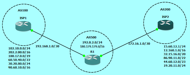
Network Topology:
 |
| MPLS Layer 3 VPN |
Creating MPLS Layer 3 VPN.7z
In the Network diagram,
- P1 and P2 are provider's core routers.
- PE1 and PE2 are provider's edge routers that connect to customer sites.
- CE1_A and CE2_A are customer edge routers of Customer-A at physically different locations.
- CE1_B and CE2_B are customer edge routers of Customer-B at physically different locations.
- Both the customers, Customer-A and Customer-B have different ASN at each location.
Configuration
P1
In the configuration, interfaces facing the core of the provider network are in OSPF area 0 and interfaces connected to the edge routers are in OSPF area 10. Also we have forcefully configured to use IP address of Loopback0 as mpls ldp router-id i.e. router ID of mpls ldp process will change immediately after executing the command, without waiting to restart the device.
hostname P1
!
ip cef
!
interface Loopback0
ip address 192.0.2.1 255.255.255.255
ip ospf 1 area 0.0.0.0
!
interface GigabitEthernet0/0
description ## Connected to PE1 G-0/0 ##
ip address 198.51.100.1 255.255.255.252
ip ospf 1 area 0.0.0.10
media-type gbic
speed 1000
duplex full
negotiation auto
mpls ip
!
interface GigabitEthernet1/0
description ## Connected to P2 G-1/0 ##
ip address 198.51.100.5 255.255.255.252
ip ospf 1 area 0.0.0.0
negotiation auto
mpls ip
!
router ospf 1
!
mpls ldp router-id Loopback0 force
P2
In the configuration, interfaces facing the core of the provider network are in OSPF area 0 and interfaces connected to the edge routers are in OSPF area 10. Also we have forcefully configured to use IP address of Loopback0 as mpls ldp router-id i.e. router ID of mpls ldp process will change immediately after executing the command, without waiting to restart the device.
hostname P2
!
ip cef
!
interface Loopback0
ip address 192.0.2.2 255.255.255.255
ip ospf 1 area 0.0.0.0
!
interface GigabitEthernet0/0
description ## Connected to PE2 G-0/0 ##
ip address 198.51.100.9 255.255.255.252
ip ospf 1 area 0.0.0.10
media-type gbic
speed 1000
duplex full
negotiation auto
mpls ip
!
interface GigabitEthernet1/0
description ## Connected to P1 G-0/0 ##
ip address 198.51.100.6 255.255.255.252
ip ospf 1 area 0.0.0.0
negotiation auto
mpls ip
!
router ospf 1
!
mpls ldp router-id Loopback0 force
PE1
Both the customers, Customer-A and Customer-B are using different ASN at each location for simplicity of configuration. We can also use same autonomous system number for a customer at all the his locations, but for that we have to use allowas-in feature on CE device. In the configuration, the device is configured with different VRFs for both the customers with route distinguisher in the form of
hostname PE1
!
ip vrf Customer-A
rd 64500:110
route-target export 64500:1000
route-target import 64500:1000
!
ip vrf Customer-B
rd 64500:120
route-target export 64500:2000
route-target import 64500:2000
!
ip cef
!
interface Loopback0
ip address 192.0.2.3 255.255.255.255
ip ospf 1 area 0.0.0.10
!
interface GigabitEthernet0/0
description ## Connected to P1 G-1/0 ##
ip address 198.51.100.2 255.255.255.252
ip ospf 1 area 0.0.0.10
media-type gbic
speed 1000
duplex full
negotiation auto
mpls ip
!
interface GigabitEthernet1/0
description ## Connected to CE1_A ##
ip vrf forwarding Customer-A
ip address 10.0.0.1 255.255.255.252
negotiation auto
!
interface GigabitEthernet2/0
description ## Connected to CE1_B ##
ip vrf forwarding Customer-B
ip address 10.0.0.5 255.255.255.252
negotiation auto
!
router ospf 1
!
router bgp 64500
bgp log-neighbor-changes
neighbor 192.0.2.4 remote-as 64500
neighbor 192.0.2.4 update-source Loopback0
!
address-family vpnv4
neighbor 192.0.2.4 activate
neighbor 192.0.2.4 send-community extended
exit-address-family
!
address-family ipv4 vrf Customer-A
neighbor 10.0.0.2 remote-as 65531
neighbor 10.0.0.2 activate
exit-address-family
!
address-family ipv4 vrf Customer-B
neighbor 10.0.0.6 remote-as 64512
neighbor 10.0.0.6 activate
exit-address-family
!
mpls ldp router-id Loopback0 force
PE2
In the configuration, the device is configured with different VRFs for both the customers with route distinguisher in the form of
hostname PE2
!
ip vrf Customer-A
rd 64500:110
route-target export 64500:1000
route-target import 64500:1000
!
ip vrf Customer-B
rd 64500:120
route-target export 64500:2000
route-target import 64500:2000
!
ip cef
!
interface Loopback0
ip address 192.0.2.4 255.255.255.255
ip ospf 1 area 0.0.0.10
!
interface GigabitEthernet0/0
description ## Connected to P2 G-0/0 ##
ip address 198.51.100.10 255.255.255.252
ip ospf 1 area 0.0.0.10
media-type gbic
speed 1000
duplex full
negotiation auto
mpls ip
!
interface GigabitEthernet1/0
description ## Connected to CE2_A ##
ip vrf forwarding Customer-A
ip address 10.1.1.1 255.255.255.252
negotiation auto
!
interface GigabitEthernet2/0
description ## Connected to CE2_B ##
ip vrf forwarding Customer-B
ip address 10.1.1.5 255.255.255.252
negotiation auto
!
router ospf 1
!
router bgp 64500
bgp log-neighbor-changes
neighbor 192.0.2.3 remote-as 64500
!
address-family ipv4
neighbor 192.0.2.3 activate
neighbor 192.0.2.4 update-source Loopback0
exit-address-family
!
address-family vpnv4
neighbor 192.0.2.3 activate
neighbor 192.0.2.3 send-community extended
exit-address-family
!
address-family ipv4 vrf Customer-A
neighbor 10.1.1.2 remote-as 65532
neighbor 10.1.1.2 activate
exit-address-family
!
address-family ipv4 vrf Customer-B
neighbor 10.1.1.6 remote-as 64513
neighbor 10.1.1.6 activate
exit-address-family
!
mpls ldp router-id Loopback0 force
All the customer edge routers are connected to ISP through a point-to-point link and using BGP for advertising their LAN segment. Loopback1 is configured to emulate inside network of customer. A default route is configured on all CE devices pointing towards ISP.
CE1_A
hostname CE1_A
!
interface Loopback1
ip address 172.16.1.1 255.255.255.0
!
interface GigabitEthernet0/0
description ## Connected to ISP ##
ip address 10.0.0.2 255.255.255.252
media-type gbic
speed 1000
duplex full
negotiation auto
!
router bgp 65531
bgp log-neighbor-changes
neighbor 10.0.0.1 remote-as 64500
!
address-family ipv4
network 172.16.1.0 mask 255.255.255.0
neighbor 10.0.0.1 activate
exit-address-family
!
ip route 0.0.0.0 0.0.0.0 10.0.0.1
CE2_A
hostname CE2_A
!
interface Loopback1
ip address 172.16.2.1 255.255.255.0
!
interface GigabitEthernet0/0
description ## Connected to ISP ##
ip address 10.1.1.2 255.255.255.252
media-type gbic
speed 1000
duplex full
negotiation auto
!
router bgp 65532
bgp log-neighbor-changes
network 172.16.2.0 mask 255.255.255.0
neighbor 10.1.1.1 remote-as 64500
!
ip route 0.0.0.0 0.0.0.0 10.1.1.1
CE1_B
hostname CE1_B
!
interface Loopback1
ip address 192.168.1.1 255.255.255.0
!
interface GigabitEthernet0/0
description ## Connected to ISP ##
ip address 10.0.0.6 255.255.255.252
media-type gbic
speed 1000
duplex full
negotiation auto
!
router bgp 64512
bgp log-neighbor-changes
network 192.168.1.0
network 192.168.1.1
neighbor 10.0.0.5 remote-as 64500
!
ip route 0.0.0.0 0.0.0.0 10.0.0.5
CE2_B
hostname CE2_B
!
interface Loopback1
ip address 192.168.2.1 255.255.255.0
!
interface GigabitEthernet0/0
description ## Connected to ISP ##
ip address 10.1.1.6 255.255.255.252
media-type gbic
speed 1000
duplex full
negotiation auto
!
router bgp 64513
bgp log-neighbor-changes
network 192.168.2.0
neighbor 10.1.1.5 remote-as 64500
!
ip route 0.0.0.0 0.0.0.0 10.1.1.5


good one
ReplyDelete