
Traffic Flow Decisions in MPLS Network
In this article, we will study how forwarding decisions are made in a MPLS Network. You can check out the configuration of the network at Creating Layer 3 MPLS VPN.
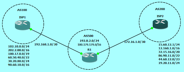
Network Topology:

Download the gns3 topology here:
Traffic Flow Decisions in MPLS Network
CE1_A#ping 172.16.2.1 source 172.16.1.1
Type escape sequence to abort.
Sending 5, 100-byte ICMP Echos to 172.16.2.1, timeout is 2 seconds:
Packet sent with a source address of 172.16.1.1
!!!!!
Success rate is 100 percent (5/5), round-trip min/avg/max = 68/88/116 ms
Yes, the destination is reachable.


Network Topology:
Traffic Flow Decisions in MPLS Network
In the given Network, We will walk along the packet sent from the inside network of CE1_A for the destination behind CE2_A, i.e. source is 172.16.1.1 and destination is 172.16.2.1.
Let’s see if the destination is reachable from source.
Type escape sequence to abort.
Sending 5, 100-byte ICMP Echos to 172.16.2.1, timeout is 2 seconds:
Packet sent with a source address of 172.16.1.1
!!!!!
Success rate is 100 percent (5/5), round-trip min/avg/max = 68/88/116 ms
Now let's walk along the packet sent from CE1_A to CE2_A. At this time the packet is at CE1_A and we have executed the command "ping 172.16.2.1 source 172.16.1.1". Below are the tables, that would be referenced to forward the packet to correct path.
To reach the destination IP address 172.16.1.1, CE1_A will reference its CEF table to forward the packets towards exit interface. CE1_A has a default route to reach the destination pointing towards 10.0.0.1, so the packets will be forwarded to 10.0.0.1 via interface GigabitEthernet 0/0.
So, from where the CEF table is built? It is built from the routing table, and we know how the routing table is built. CEF table is built by extracting the required details from various tables on a router, one of which is routing table. CEF takes next hop for all the destinations and do a recursive lookup to find the exit interfaces.
Now, the packet reaches at PE1. Let's check out what tables PE1 will reference to forward the packets further.
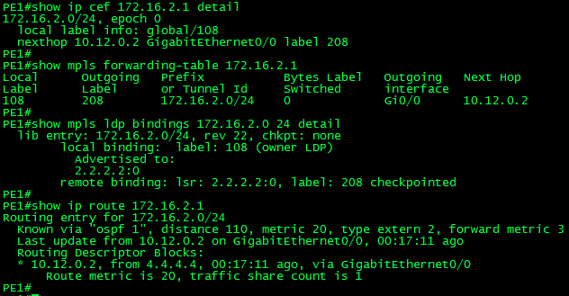
To forward the packets destined to 172.16.2.1, PE1 will reference its CEF table to find out the exit interface. After analyzing the CEF table PE1 will find out the exit interface and also the mpls label information, i.e. which label to remove and which to impose. In this case PE1 will impose the label 208 before forwarding it to the nexthop out of interface GigabitEthernet 0/0.
So, from where the CEF table get the information of Label Forwarding Information Base? It gets this detail from the mpls forwarding-table, which is the LFIB of MPLS. MPLS forwarding-table has an entry for every prefix contained in the routing table with the corresponding local label, outgoing label, outgoing interface and IP next hop.
MPLS forwarding table (LFIB) is built by referencing mpls ldp binding table and routing table. mpls ldp binding table lookup is done to find out the label assigned by the downstream lsr. And routing table lookup is done to find out the IP next hop address, which will be used to find out the layer 2 address of the peer LSR for forwarding the frames.
Now, the packet reaches at P1. Let's check out how P1 will make decision to forward the packets further.
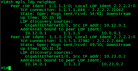
P1 will also forward the packet based on the information collected by CEF table. But look at the output of show mpls ldp bindings 172.16.2.0 24 detail above, P1 has two remote binding for the network 172.16.2.0/24. P1 is receiving labels from both the peer LSRs i.e. PE1 (1.1.1.1) and P2 (3.3.3.3), implying that the prefix 172.16.2.0/24 is reachable via both LSRs. But P1 has only added the label received from P2 to its mpls forwarding-table (LFIB).
So how P1 decided to add only the label received from P2 to mpls forwarding-table? The answer is routing table. When P1 sees two remote bindings for a prefix, it will do a recursive lookup of routing table to find the best path to reach the destination. In this case P1 finds the best path via 10.23.0.2 (3.3.3.3). Below is the mpls ldp neighbor table of P1, which shows the peer LDP Identity along with the peer IP address.
Now the packet reaches P2, It will also follow the same steps as P1 to make the forwarding decision. P2 will reference its CEF table and find out that packets destined to 172.16.2.1 should be forwarded with a label of 408 to the nexthop 10.34.0.2 out of interface GigabitEthernet0/0.
After passing through the P2, packet reaches PE2. PE2 will also reference it's CEF table and find out that the packets destined to 172.16.2.1 should be forwarded to the next hop 10.1.1.2 out of interface GigabitEthernet1/0 without any label, i.e. PE2 will remove the label 408 before forwarding it to CE2_A
Now the packet will reach CE2_A, where CEF table will be referenced for the further path. After referencing the CEF table, CE2_A finds that the destination prefix is directly connected and the IP address is configured locally. So the router will accept the packet and process it.
So, above are the steps that are followed during decision making for forwarding of mpls packets.
Also, it is good to know that for forwarding the frames to next hop, mpls don't have to send arp requests to find the next hop layer 2 address. As all the forwarding has to be done before layer 3 in mpls, mpls stores the next hop layer 2 address in LFIB i.e. mpls forwarding table. Below is an example.
Some basic show commands in mpls environment.
# show ip cef
# show mpls forwarding-table
# show mpls ldp bindings
# show ip route
# show mpls ldp neighbor
# show mpls ip binding
# show mpls interfaces
# show mpls forwarding-table
# show mpls ldp bindings
# show ip route
# show mpls ldp neighbor
# show mpls ip binding
# show mpls interfaces
Summary
The traffic flow decision is made by referencing the FIB. Below are the different tables used in MPLS in a sequence of which table is build referencing which table, e.g. FIB is build using information from LFIB
FIB - Forwarding Information Base - show ip cef
LFIB - Label Forwarding Information Base - show mpld forwarding table
LIB - Label Information Base - show mpls ldp bindings
RIB - Routing Information Base - show ip route


Comments
Post a Comment