
Spanning Tree Protocol Operation
Whenever there is redundancy in the network, there are chances of formation of loops. When loops are at layer 3, TTL value in the packet header saves the packet from looping endlessly. Similarly, to avoid loops at layer 2, Spanning Tree Protocol (STP) comes into play. STP exchanges BPDU messages with other switches to detect loops, and then removes the loop by shutting down selected bridge interfaces. This algorithm guarantees that there is only one active path between two network devices. A layer 2 network with redundancy without STP can cause following issues:
Consider the example in which there are three bridges, A, B and C connected with each others
- Broadcast Storm
- Unstable mac-address table in a switch
- Duplicate frames arriving at host
STP Operation
Election of Root Bridge
With STP, the key is for all the switches in the network to elect a root bridge that becomes the focal point in the network. All other decisions in the network, such as which port to block and which port to put in forwarding mode, are made from the perspective of this root bridge. Each VLAN must have its own root bridge because each VLAN is a separate broadcast domain. The roots for the different VLANs can all reside in a single switch or in various switches.
Below are the attributes for election of a root bridge
Below are the attributes for election of a root bridge
• Prefer the switch with lower priority. (Default is 32768 + sys-id-ext)
• Prefer the switch with lower mac-address
• Prefer the switch with lower mac-address
We can influence the root bridge election process by changing the priority of the switch using the command
switch(config)# spanning-tree vlan x priority 4096Bridge priority must be in increments of 4096.

At the bootup, all of the bridges think of themselves as the Root Bridge

Assume that the first step is that Bridge C sends the BPDU to Bridges A and B, announcing that bridge C is the Root, with Root ID of 32768.00-00-00-00-00-02

Note that Bridge B's Root ID changed from 03 to 02. Also Note that Bridge A's Root ID did not change.
Considering that Bridge B's Bridge ID is greater than the Root ID it sees in the BPDU, Bridge B accepts that C is the Root. Now Bridge B will start forwarding BPDUs received from the Root Bridge.
Bridge A still considers itself as the Root as its Bridge ID is less than the Root ID it sees in the BPDU. Bridge C still thinks of itself as the Root.

Assume that the next step is for Bridge A to send BPDUs towards Bridge B and C announcing itself as the root. Bridge A's Root ID is 32768.00-00-00-00-00-01

Note the change in B and C's Root IDs to 01
All bridges are now in agreement that Bridge A is the Root Bridge. Now all the non-root bridges will start relaying BPDUs received from the Root Bridge.


Port states and BPDUs
STP Default Timers:
Forward delay time 15 seconds
Hello time 2 seconds
Maximum aging time 20 seconds
The above default values are derived from the below expressions and change if any corresponding value changes in the expression.
max_age = (4 x hello) + (2 x diameter) – 2
forward_delay = ((4 x hello) + (3 x diameter)) / 2
Diameter is the number of hops in the network between two points and is set to 7 by default.
Related Articles
http://blog.ine.com/2009/03/07/understanding-stp-convergence-part-i/
Assume that the first step is that Bridge C sends the BPDU to Bridges A and B, announcing that bridge C is the Root, with Root ID of 32768.00-00-00-00-00-02
Note that Bridge B's Root ID changed from 03 to 02. Also Note that Bridge A's Root ID did not change.
Considering that Bridge B's Bridge ID is greater than the Root ID it sees in the BPDU, Bridge B accepts that C is the Root. Now Bridge B will start forwarding BPDUs received from the Root Bridge.
Bridge A still considers itself as the Root as its Bridge ID is less than the Root ID it sees in the BPDU. Bridge C still thinks of itself as the Root.
Assume that the next step is for Bridge A to send BPDUs towards Bridge B and C announcing itself as the root. Bridge A's Root ID is 32768.00-00-00-00-00-01
Note the change in B and C's Root IDs to 01
All bridges are now in agreement that Bridge A is the Root Bridge. Now all the non-root bridges will start relaying BPDUs received from the Root Bridge.
Election of Root Port
Every non-root bridge must select one Root port. A bridge's root port is the port closest to the Root bridge. Non-root Bridges elect their respective root port based on the Root path Cost, which is the cumulative cost of all links to the root bridge. In the above example, Switch A will be the Root Bridge and it will send BPDUs out its interfaces every 2 Seconds with Root Path Cost of 0 as all its ports are attached to itself. Upon the receiving the BPDU Switch B and C will add the Path Cost before forwarding it out to other bridges.
Below are the attributes for election of a root port
• Prefer the port which provides lowest cost to reach the root bridge
• Prefer the switch with lower bridge id (if there are more than one port that provide the same cost to reach the root bridge).
• Prefer the port which is receiving lower port priority from the designated switch (if the same designated switch is providing two paths to reach the root bridge, i.e. the switch has two parallel links connected to the designated switch). Default port priority is 128.
Moving forward with the same example,
Assuming that all links between the bridges have the same speed (say 100 Mbps with a cost of 19, according to IEEE), Bridge B and Bridge C elect their Root ports
Election of Designated Ports
Facts about designated ports:
- The Port that advertises the lowest Root Path Cost onto the segment is elected as Designated Port
- Designated port forwards traffic away from the root bridge.
- There can be only one designated port per segment/link.
- The bridge containing the designated port for a given segment is referred to as the designated bridge for that segment.
There are three segments i.e. segment 1,2 and 3 in the same scenario.
Since the port on Bridge A are directly connected to the Root Bridge, these ports become the designated ports for Segment 1 and Segment 2.
The path cost to the root bridge is the same for Bridge B and Bridge C. The tie breaker is the lower bridge ID of Bridge C. Since the bridge ID of Bridge C is less than the bridge ID of Bridge B, the designated port for Segment 3 becomes port 1/2 of Bridge C
Root ports and the designated ports go into the forwarding states. Ports that are neither the root ports nor the designated ports, in other words ports that are non-designated ports, go to the blocking state.
At this point, Spanning tree has fully converged.
Bridge C has a better BPDU than Bridge B. So, Bridge C continues to send BPDUs advertising its superiority over Bridge B. As long as Bridge B continues to receive these Superior BPDUs on port 1/2, the port remains in the Blocking mode.
For any reason if Bridge B fails to receive these BPDUs for max age time, which is 20 seconds by default, it would start transition to the forwarding mode. Most of the Spanning Tree Algorithm (STA) failures occur due to the excessive loss of BPDUs causing the blocked ports to transition to forwarding mode. Some of the situations in which the loss of BPDUs cause a blocked port to go into forwarding mode are:
- Duplex Mismatch
- Unidirectional Link
- Packet Corruption
- Resource Errors
- Portfast Configuration Error
- Awkward STP Parameter Tuning and Diameter Issue
- Software Errors
Optional STP Features
PortFast
STP PortFast causes a Layer 2 LAN port configured as an access port to enter the forwarding state immediately, bypassing the listening and learning states. When configured for PortFast, a port is still running the spanning tree protocol. A PortFast enabled port can immediately transition to the blocking state if necessary (this could happen on receipt of a superior BPDU).
This feature can be enabled by using the spanning-tree portfast interface configuration or the spanning-tree portfast default global configuration command.
Portfast can also be configured on Trunk interfacers using the command spanning-tree portfast trunk. Use this with Caution.
This feature can be enabled by using the spanning-tree bpduguard enable interface configuration or the spanning-tree portfast bpduguard default global configuration command.
When enabled globally, BPDU Guard applies to all interfaces that are in an operational PortFast (edge) state.
When STP BPDU guard disables the port, the port remains in the disabled state unless the port is enabled manually. You can configure a port to reenable itself automatically from the errdisable state. Issue these commands, which set the errdisable-timeout interval and enable the timeout feature:
This feature can be enabled by using the spanning-tree bpdufilter enable interface configuration or the spanning-tree portfast bpdufilter default global configuration command.
Configuring BPDU filter globally and at interface level has different affects.
When configured globally, if an operational PortFast port receives a BPDU, it immediately loses its operational PortFast status and becomes a normal port.
When PortFast BPDU filtering is explicitly configured on a port, it does not send any BPDUs and drops all BPDUs it receives. This may cause bridging loops, so be cautious.
• The unique bridge ID (switch priority and MAC address) associated with each VLAN on each switch
• The spanning-tree path cost to the root switch
• The port identifier (port priority and MAC address) associated with each Layer 2 interface
There are two types of BPDUs:
Each configuration BPDU contains this information:
• Type: Determines which of the two BPDU formats this frame contains (Configuration BPDU or TCN BPDU)
• Root ID: COntains the Bridge ID of the Root Bridge. After convergenc, all Configuraiton BPDUs in the bridged network should contain the same value for this field (for a single VLAN).
• Root Path Cost: The cumulative cost of all links leading to the Root Bridge.
• Sender Bridge ID: The bridge ID of the sending switch.
• Port Identifier: contains a unique value for every port. It is the combination of port priority and port number. Default port priority is 128.
• Message Age: The message age contains the length of time that has passed since the root bridge initially originated the BPDU. The root bridge sends all its BPDUs with a message age value of 0, and all subsequent switches add 1 to this value. Effectively, this value contains the information on how far you are from the root bridge when you receive a BPDU i.e. how many hops away a bridge is from the root bridge.
• Hello Time: The hello time is the time between each BPDU that is sent on a port. This time is equal to 2 seconds by default, but you can tune the time to be between 1 and 10 sec.
• forward delay: The forward delay is the time that is spent in the listening and learning state. This time is equal to 15 sec by default, but you can tune the time to be between 4 and 30 sec.
When a switch receives a configuration BPDU that contains superior information (lower bridge ID, lower path cost, and so forth), it stores the information for that port. If this BPDU is received on the root port of the switch, the switch also forwards it with an updated message to all attached LANs for which it is the designated switch.
If a switch receives a configuration BPDU that contains inferior information to that currently stored for that port, it discards the BPDU. If the switch is a designated switch for the LAN from which the inferior BPDU was received, it sends that LAN a BPDU containing the up-to-date information stored for that port. In this way, inferior information is discarded, and superior information is propagated on the network.
Importance of Topology Change Notification
By default mac-address-table aging time is 300 seconds (5 minutes). Consider a situation where there is a change in spanning tree topology due to some link failure, in that case there may be some bridges which will cause the traffic to be blackholed by forwarding based on their existing mac-address-table.
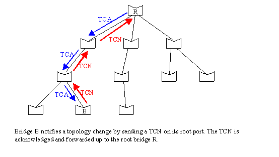
To avoid this situation there there has to be some way to reduce the aging time of mac-address-table when there is a STP topology change, and here the TCN BPDU comes into picture. Configuration BPDUs are sent out of Designated ports, i.e. away from the root bridge, while the TCN BPDUs are sent out of root ports towards the root bridge. A TCN is generated whenever some port (not configured with portfast) changes it's state (up/down). When a switch detects a change in a port state, it sends a TCN out of root port towards the root bridge. The designated bridge receives the TCN, acknowledges the TCN with TCA (Topology Change Acknowledgement) and relays the TCN towards root bridge out of it's root port. This process continues until the TCN reaches the root bridge. Once the root bridge receives a TCN, it starts sending TCA out of it's designated port where the TCN was received for a time of max_age + forward_delay (20_15 sec). In this way all the downstream bridges receives TCA BPDU and sets the aging time of mac-address-table equals to forward_delay i.e. 15 seconds.
Portfast can also be configured on Trunk interfacers using the command spanning-tree portfast trunk. Use this with Caution.
BPDU Guard
BPDU Guard complements the functionality of PortFast. PortFast BPDU guard prevents loops by moving a portfast enabled port into an errdisable state when a BPDU is received on that port. When you enable BPDU guard on the switch, spanning tree shuts down PortFast-configured interfaces that receive BPDUs instead of putting them into the spanning tree blocking stateThis feature can be enabled by using the spanning-tree bpduguard enable interface configuration or the spanning-tree portfast bpduguard default global configuration command.
When enabled globally, BPDU Guard applies to all interfaces that are in an operational PortFast (edge) state.
When STP BPDU guard disables the port, the port remains in the disabled state unless the port is enabled manually. You can configure a port to reenable itself automatically from the errdisable state. Issue these commands, which set the errdisable-timeout interval and enable the timeout feature:
Note: The default timeout interval is 300 seconds and, by default, the timeout feature is disabled(config)# errdisable recovery cause bpduguard(config)# errdisable recovery interval 400
BPDU Filter
PortFast BPDU filtering prevents the system from sending or even receiving BPDUs on specified ports, depending on the configuration.This feature can be enabled by using the spanning-tree bpdufilter enable interface configuration or the spanning-tree portfast bpdufilter default global configuration command.
Configuring BPDU filter globally and at interface level has different affects.
When configured globally, if an operational PortFast port receives a BPDU, it immediately loses its operational PortFast status and becomes a normal port.
When PortFast BPDU filtering is explicitly configured on a port, it does not send any BPDUs and drops all BPDUs it receives. This may cause bridging loops, so be cautious.
Spanning Tree Topology and BPDUs
The stable, active spanning-tree topology of a switched network is determined by these elements:• The unique bridge ID (switch priority and MAC address) associated with each VLAN on each switch
• The spanning-tree path cost to the root switch
• The port identifier (port priority and MAC address) associated with each Layer 2 interface
There are two types of BPDUs:
- Configuration BPDUs
- Topology Change Notification BPDUs
Each configuration BPDU contains this information:
• Type: Determines which of the two BPDU formats this frame contains (Configuration BPDU or TCN BPDU)
• Root ID: COntains the Bridge ID of the Root Bridge. After convergenc, all Configuraiton BPDUs in the bridged network should contain the same value for this field (for a single VLAN).
• Root Path Cost: The cumulative cost of all links leading to the Root Bridge.
• Sender Bridge ID: The bridge ID of the sending switch.
• Port Identifier: contains a unique value for every port. It is the combination of port priority and port number. Default port priority is 128.
• Message Age: The message age contains the length of time that has passed since the root bridge initially originated the BPDU. The root bridge sends all its BPDUs with a message age value of 0, and all subsequent switches add 1 to this value. Effectively, this value contains the information on how far you are from the root bridge when you receive a BPDU i.e. how many hops away a bridge is from the root bridge.
• Hello Time: The hello time is the time between each BPDU that is sent on a port. This time is equal to 2 seconds by default, but you can tune the time to be between 1 and 10 sec.
• forward delay: The forward delay is the time that is spent in the listening and learning state. This time is equal to 15 sec by default, but you can tune the time to be between 4 and 30 sec.
When a switch receives a configuration BPDU that contains superior information (lower bridge ID, lower path cost, and so forth), it stores the information for that port. If this BPDU is received on the root port of the switch, the switch also forwards it with an updated message to all attached LANs for which it is the designated switch.
If a switch receives a configuration BPDU that contains inferior information to that currently stored for that port, it discards the BPDU. If the switch is a designated switch for the LAN from which the inferior BPDU was received, it sends that LAN a BPDU containing the up-to-date information stored for that port. In this way, inferior information is discarded, and superior information is propagated on the network.
Importance of Topology Change Notification
By default mac-address-table aging time is 300 seconds (5 minutes). Consider a situation where there is a change in spanning tree topology due to some link failure, in that case there may be some bridges which will cause the traffic to be blackholed by forwarding based on their existing mac-address-table.
To avoid this situation there there has to be some way to reduce the aging time of mac-address-table when there is a STP topology change, and here the TCN BPDU comes into picture. Configuration BPDUs are sent out of Designated ports, i.e. away from the root bridge, while the TCN BPDUs are sent out of root ports towards the root bridge. A TCN is generated whenever some port (not configured with portfast) changes it's state (up/down). When a switch detects a change in a port state, it sends a TCN out of root port towards the root bridge. The designated bridge receives the TCN, acknowledges the TCN with TCA (Topology Change Acknowledgement) and relays the TCN towards root bridge out of it's root port. This process continues until the TCN reaches the root bridge. Once the root bridge receives a TCN, it starts sending TCA out of it's designated port where the TCN was received for a time of max_age + forward_delay (20_15 sec). In this way all the downstream bridges receives TCA BPDU and sets the aging time of mac-address-table equals to forward_delay i.e. 15 seconds.
Spanning Tree Port States
Each Layer 2 interface on a switch using Spanning Tree Protocol (STP) exists in one of the following states:
• Disabled—The Layer 2 interface does not participate in spanning tree and is not forwarding frames.
• Blocking—The Layer 2 interface does not participate in frame forwarding.
• Listening—First transitional state after the blocking state when spanning tree determines that the Layer 2 interface must participate in frame forwarding.
• Learning—The Layer 2 interface prepares to participate in frame forwarding.
• Forwarding—The Layer 2 interface forwards frames.
Blocking State
A Layer 2 interface in the blocking state performs as follows:
• Discards frames.
• Does not incorporate end station location into its address database. (There is no learning on a blocking Layer 2 interface, so there is no address database update.)
• Does not transmit BPDUs received from the system module.
• Receives BPDUs and directs them to the system module.
Listening State
A Layer 2 interface in the listening state performs as follows:
• Discards frames.
• Does not incorporate end station location into its address database. (There is no learning)
• Transmits BPDUs received from the system module.
• Receives and directs BPDUs to the system module.
Learning State
A Layer 2 interface in the learning state performs as follows:
• Discards frames.
• Incorporates end station location into its address database.
• Transmits BPDUs received from the system module.
• Receives BPDUs and directs them to the system module.
Forwarding State
A Layer 2 interface in the forwarding state performs as follows:
• Forwards frames.
• Incorporates end station location information into its address database.
• Transmits BPDUs received from the system module.
• Receives BPDUs and directs them to the system module.
Disabled State
A Layer 2 interface in the disabled state performs as follows:
• Discards frames.
• Does not incorporate end station location into its address database. (There is no learning)
• Does not receive BPDUs for transmission from the system module.
Port states and BPDUs
Port State | Transmits BPDUs | Accepts BPDUs | ||
Disabled | û | û | ||
Blocking | û | ü | ||
Listening | ü | ü | ||
Learning | ü | ü | ||
Forwarding | ü | ü | ||
STP Default Timers:
Forward delay time 15 seconds
Hello time 2 seconds
Maximum aging time 20 seconds
The above default values are derived from the below expressions and change if any corresponding value changes in the expression.
max_age = (4 x hello) + (2 x diameter) – 2
forward_delay = ((4 x hello) + (3 x diameter)) / 2
Diameter is the number of hops in the network between two points and is set to 7 by default.
Related Articles
http://blog.ine.com/2009/03/07/understanding-stp-convergence-part-i/


Comments
Post a Comment